


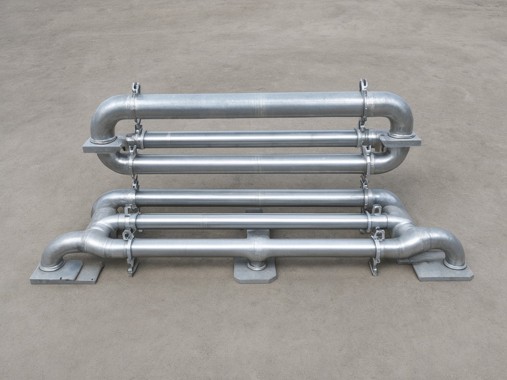
China industrial pipe hangers and supports manufacturer: Specification, Ordering and Quality Notes
Design Constraints Behind the Specification
The build method decides how a pipe support carries load and where wear starts. Formed and stamped steel suits repeatable hanger and clamp profiles; welded assemblies allow thicker sections, brackets and custom connection points. For a second-source review, compare the drawing, material thickness, hole position and weld details—not just the product name.
Load capacity depends on the support geometry, fasteners, attachment substrate, pipe contents, temperature and installed spacing. A factory should not assign a working-load figure from material grade alone. Durability also depends on the exposure: outdoor UV affects some organic coatings, while washdown, chloride exposure and trapped moisture can accelerate corrosion at edges, seams and damaged coating.
Material Thickness
Common fabricated parts use roughly 2–10 mm sheet or plate, subject to part size, formed profile and specified load case.
Joining Method
Formed one-piece parts reduce weld-dependent variation; welded frames accommodate larger offsets and multi-piece configurations.
Surface Protection
Zinc coatings suit many general environments; stainless steel or a specified protective coating may be needed for persistent moisture or chemical exposure.
Specify the exposure and load case together. A coating selection cannot compensate for an unsuitable support section, and a load rating is meaningful only with its mounting and test conditions defined.
Matching the Product to the Buyer's Need
Process choice shows up later as fit-up time, coating life and the frequency of dimensional corrections during installation. A formed clevis hanger or pipe clamp can be economical at repeat volume, while a fabricated trapeze or offset bracket carries more welding and handling cost. That added work is justified when the assembly must match a defined span, connection pattern or field clearance.
Use the specification table as a sourcing starting point, not as a load approval. Nominal pipe size does not establish the actual clamp opening, insulation allowance or finished assembly weight. Confirm those dimensions against the buyer's drawing and installation condition before sample release.
| Specification | Typical supply range | Buyer confirmation point |
|---|---|---|
| Nominal pipe size coverage | About DN 15–DN 300, depending on hanger or support design | Pipe outside diameter, insulation thickness and required clearance |
| Part thickness and weight | Typically 2–10 mm material; finished weight varies by geometry and hardware | Drawing thickness, assembly contents and permitted weight tolerance |
| Material options | Carbon steel; stainless steel grades such as 304 or 316 where specified | Corrosion exposure, compatible fasteners and required material documentation |
| Finish options | Electrogalvanized, hot-dip galvanized or specified powder / protective coating | Coating coverage at cut edges, welds and contact surfaces; agreed thickness or test criteria |
OEM and ODM Programme Structure
First-article tooling determines whether a repeat order holds the approved profile, hole positions and formed angles. For an OEM transfer, provide controlled drawings, revision status, material and finish requirements, plus any assembly or packaging instructions. The factory can then assess whether existing dies and fixtures suit the part or whether new tooling is required.
Drawing-Led OEM
Best fit when dimensions and interfaces are already fixed. Approval should cover a first article, finish appearance, critical dimensions and the packing configuration used for shipment.
Joint ODM Development
Useful when the required support geometry is known but the buyer needs design input. The project should settle load assumptions, installation interfaces, material, corrosion protection and drawing ownership before production tooling begins.
For a second-source qualification, retain the approved sample reference and revision-controlled inspection criteria. If the source change includes a different coating route or weld sequence, review that process difference before authorizing a production lot.
Inspection Items and Test Methods
Inspection should concentrate on features that affect installation or service life. A clean-looking coating does not confirm coverage inside a bend or around a weld, and a dimensional pass does not validate the assembly's load capacity.
- Check material thickness, hole location, formed profile, clamp opening and overall dimensions against the released drawing.
- Inspect weld continuity and visible defects; use an agreed weld inspection method where the joint is load-bearing.
- Verify coating coverage and thickness against the purchase specification, with additional corrosion testing only when the buyer defines the method and acceptance criteria.
- Run assembly or proof-load checks only to an approved fixture, load case and acceptance limit; record lot identity and sample quantity.
- Review packaging for coating rub, bent threaded parts and movement between nested components after transit simulation or agreed shipment checks.
Salt spray exposure can compare coating systems under a defined laboratory method, but it does not directly predict field life. For outdoor storage or repeated washdown, agree on the coating system, edge coverage and inspection evidence before the production order.
Volume Planning and Lead Time
Lead time depends on drawing release, tooling status, steel availability, surface-treatment route and inspection scope. Existing formed parts can move faster than a new welded assembly that needs fixture development and a load-test setup. A firm schedule should separate sample approval from production and export packing.
For repeat supply, share forecast volume, order release frequency, packaging limits and buffer-stock expectations during quotation. Nested parts reduce freight volume, but separators may be needed to prevent coating abrasion; threaded rods and loose hardware should be secured to avoid impact damage in transit. A second-source plan also benefits from an agreed change-notification process for material, finish or production-route changes.
Discuss the source-qualification scope. Send the drawing revision, target annual volume, exposure conditions, required inspection records and current supply constraint for a focused feasibility review.
Contact the team to discuss your pipe hanger and support programme.