


Custom u bolt for 1 1 4 pipe manufacturer: Specification, Ordering and Quality Notes
Selection rule: specify the pipe’s actual outside diameter, not just “1 1/4 pipe.” A carbon-steel U-bolt usually costs less; stainless or a protective finish adds material or process cost where corrosion exposure warrants it. Agree on inside width, leg length, thread, finish and fit sample before releasing repeat orders.
The complaint that repeats across reorders is a U-bolt that fits the first pipe sample but not the next installation lot. For a second source, the drawing must define the pipe standard and outside diameter alongside the U-bolt dimensions; the nominal size alone leaves room for a fit dispute.
Scope of Supply and Physical Form
A U-bolt for nominal 1 1/4-inch pipe is a formed round-bar fastener with two threaded legs. For common NPS pipe, 1 1/4 inch corresponds to a nominal outside diameter of 1.660 inches (42.2 mm); confirm the pipe specification before setting the inside width. Wall schedule generally changes the bore, not the outside diameter, but other tube or conduit families may use different sizing conventions.
Supply can cover the formed fastener alone or a matched set with nuts and washers. Define whether the inside width is measured between the legs at the bend, and call out leg length, bar diameter, bend radius, thread diameter and usable thread length on the released drawing.
Materials and Construction Trade-offs
Carbon steel is the cost-conscious choice for dry or protected installations, subject to the specified strength and finish. Stainless steel costs more and may suit wet or corrosive service; grade selection still depends on the actual exposure, including chemicals and cleaning agents. A coating does not replace the need to select a suitable base material.
| Finish and appearance | Typical use and trade-off | Fit note for the order |
|---|---|---|
| Electroplated zinc; usually silver-toned | A lower-cost coating for indoor or less exposed service. Coating wear and exposure conditions affect corrosion protection. | Confirm coating specification and nut fit after plating. |
| Hot-dip galvanized; matte grey | A thicker zinc layer can suit more exposed installations, with added coating thickness and a less uniform surface appearance. | Allow for coating build on threads; agree nut clearance and finish requirements in advance. |
| Passivated stainless; natural metallic finish | Avoids a separate metallic coating; material cost is higher, and the selected grade must match the service environment. | State the stainless grade and whether nuts and washers must match. |
| Plain or lightly oiled steel; dark or untreated appearance | Avoids coating cost where the part receives a separate finish or remains in protected service; it offers little protection from moisture during storage. | Set packaging and storage expectations to limit surface rust before installation. |
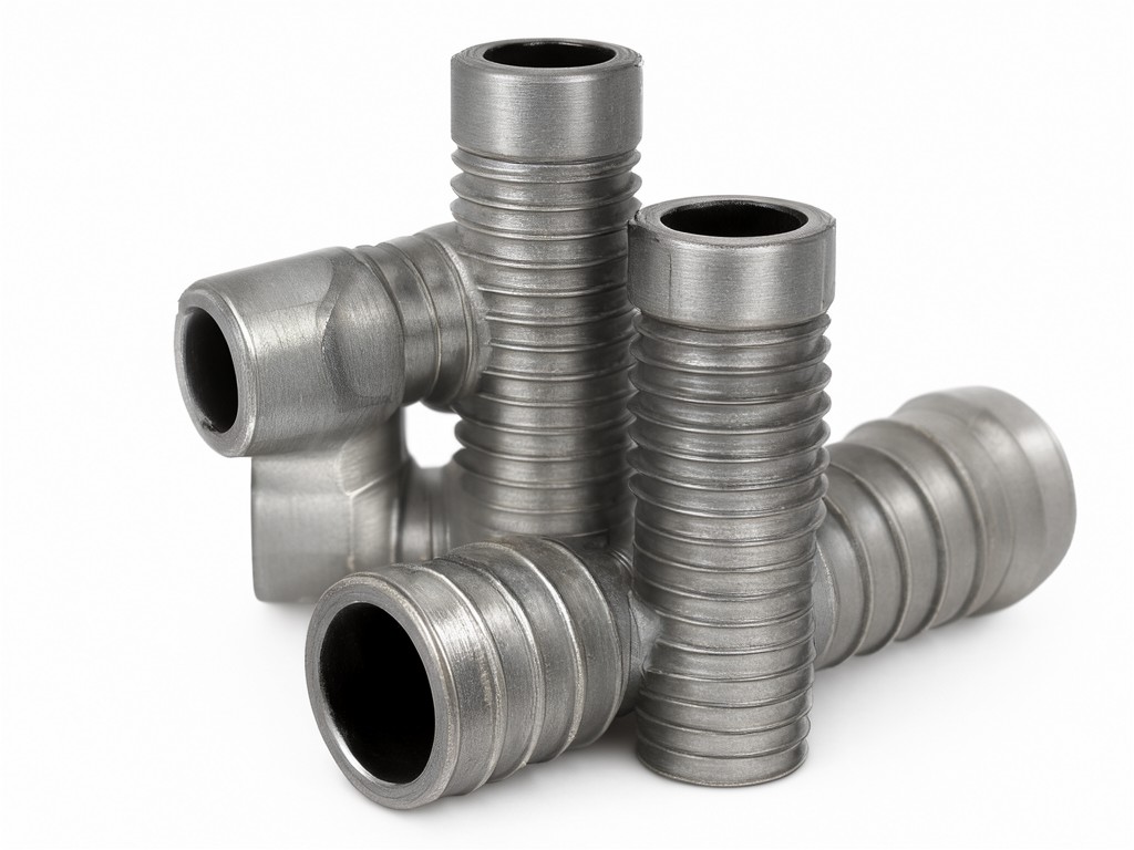
Colour can vary by finish and production lot, especially on plated or galvanized parts. If appearance is a purchasing requirement, approve a finish sample and define acceptable variation rather than relying on a colour name alone.
How It Is Built and What That Changes
For this size range, a typical route starts with round bar cut to length, followed by controlled bending around a former. The bend radius and forming setup affect the inside width and leg alignment; a change in bar diameter or material may require a revised setup rather than a direct tooling substitution.
The legs are trimmed and threaded, then the specified finish is applied. Threading method and finish sequence can affect usable thread length and nut engagement. A production drawing should show the finished-part dimensions, with any coating allowance accounted for where threads or tight clearances are involved.
For a source change, approve a formed sample against the same drawing and pipe section used for the existing part. That check catches differences in bend geometry and assembly clearance before a batch is committed.
Measured Performance in Real Use
Fit is judged at the pipe, not by the nominal label. Check inside width, leg spacing, bend symmetry, bar diameter and thread engagement against the approved drawing and mating hardware. A U-bolt that is too tight can be difficult to assemble; excess clearance can shift the clamp position or change how the load is carried.
Do not assign a load rating from pipe size alone. Load capacity depends on bar material and diameter, leg and bend geometry, installation method, mating plate and the supported system. Set the design load and tightening procedure with the responsible engineer; avoid overtightening against thin-wall pipe.
For repeat supply, record the accepted dimensional basis and finish with the sample approval. Batch checks can then use those agreed dimensions and the buyer’s specified inspection plan; no single test result substitutes for a defined application load.
OEM and ODM Programme Structure
An OEM programme can begin from a released customer drawing, a physical reference part or both. The supplier should map each reference dimension to a measurable feature, flag any missing tolerance, and issue a controlled drawing for review. Where the supplied part and drawing disagree, resolve the difference in writing before sample production.
For an ODM arrangement, the buyer and manufacturer establish the geometry and material from the application details. A practical approval sequence is drawing review, first sample fit check, finish approval, then written sign-off of the production baseline. Keep revision identifiers with the order so a later reorder does not rely on an unmarked sample.
Agree packaging quantity, corrosion protection in transit, carton identification and batch traceability at quotation stage. These details help a second source deliver parts that receiving staff can identify and compare without changing the installation process.
Setup, Use and Replacement Parts
Fit the U-bolt with the specified saddle or mounting plate and use compatible nuts and washers. Tighten evenly to the installation procedure for the supported assembly; excessive torque can damage threads or deform pipe, while uneven tightening can leave the clamp skewed.
Inspect for corrosion, thread damage, looseness or permanent deformation during scheduled maintenance. Replace a part that has cracked, bent out of shape or lost secure thread engagement. If the installation uses a coating, damage at the contact points may expose the base metal and should be assessed against the service conditions.
Ordering, Tooling and Lead-Time Questions
What dimensions should be on the first drawing?
Include pipe standard and outside diameter, bar diameter, inside width, inside bend radius, leg length, thread diameter and pitch, usable thread length, material, finish and tolerances. Identify whether dimensions apply before or after coating where that affects fit.
Can a reference sample replace a drawing?
A sample helps establish form and assembly fit, but it does not define every tolerance or material requirement. Use it with a dimensioned drawing, or have the supplier measure it and submit a drawing for buyer approval before production.
What affects MOQ and lead time for a second source?
Bar availability, bend setup, thread tooling, finish batch size and sample approval all affect the schedule and order quantity. Share the annual forecast, initial release quantity and required finish at quotation review so setup and replenishment terms can be evaluated together.
For a quotation review, send the drawing or reference part details, pipe specification, finish, forecast quantity and sample approval requirements. Contact us to review the specification and second-source plan.