


Custom u bolt guide support factory: What Buyers Should Check Before Ordering
Selection trade-off: A close guide clearance controls lateral pipe movement, but it must still allow the specified axial travel during thermal expansion. Confirm pipe outside diameter, insulation or liner thickness, operating movement and attachment details before fixing the U-bolt and guide dimensions.
The interface between parts determines whether a guide restrains sideways movement without binding the pipe as it expands. A fabricated assembly may include a U-bolt, guide plates or lugs, and a base or attachment plate; the exact arrangement follows the support drawing and installation location. For repeat orders, freeze the drawing revision, material, finish and supplied hardware as one controlled configuration.
Scope of Supply and Physical Form
Balance and load analysis shows why pipe size alone is not enough to define the assembly. The order should identify the pipe outside diameter, guide gap, U-bolt rod diameter and thread, plate geometry, attachment method, and any insulation or wear pad within the guide. If any of these interfaces change between purchase orders, the fit and lateral restraint can change with them.
| Size or weight item | Order basis | What changes the range |
|---|---|---|
| Pipe and guide size | Dimension to the approved drawing; state pipe outside diameter and any insulation or liner thickness. | Guide clearance, required lateral restraint, and movement allowance. |
| U-bolt and plate dimensions | Specify rod diameter, thread and plate or lug dimensions for the service load and connection. | Material grade, formed geometry, weld details and finish allowance. |
| Assembly weight | Confirm from the final bill of materials and approved configuration; there is no single weight range for custom assemblies. | Rod and plate thickness, support geometry, hardware and coating build. |
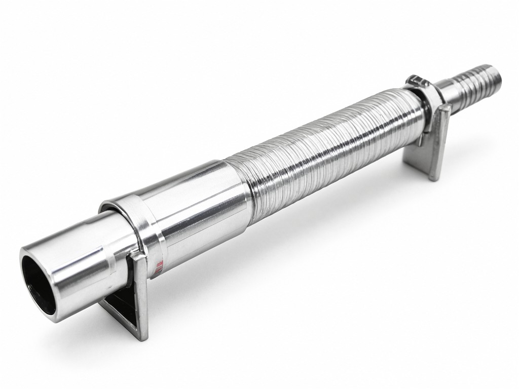
A quoted unit weight is useful for freight planning and incoming checks, but it only remains meaningful while the material and drawing revision stay fixed.
How It Performs in Use
Deflection under load governs the required plate, rod and attachment design. The guide should limit lateral movement at the specified load while leaving the pipe free to travel along its axis where the system design calls for thermal movement. A gap that is too tight can cause binding or abrasion; one that is too wide can allow impact and repeated contact.
Fabrication checks should focus on dimensions that control fit: U-bolt inside width, thread condition, guide spacing, plate flatness and weld location. Where the support carries a defined load, review the material, connection and weld details against the project design rather than treating a generic U-bolt size as a load rating. The decision rule is to approve both the restraint direction and the permitted movement on the drawing.
Segment-Specific Requirements
Outdoor pipework needs a finish suited to moisture, UV exposure and the site’s maintenance routine. UV does not degrade the steel itself, but it can affect exposed polymer liners or pads; specify their material and replacement method if they are part of the assembly. For chlorine-bearing washdown or other corrosive cleaning exposure, confirm the actual chemical concentration and contact conditions before selecting stainless steel, a protective coating or another finish.
Abrasion at the guide surface can remove coating and expose base metal, particularly where clearance allows repeated contact. A replaceable wear element may reduce support replacement cost, while a simpler steel-to-steel design has fewer parts to track. Choose the arrangement around inspection access, expected movement and the site’s spare-parts practice.
Repeat-order control: Record the approved material and finish alongside the drawing revision. A finish substitution can alter corrosion resistance, dimensions at mating surfaces and the way replacement parts fit.
Packing, Marking and Freight Configuration
Thread damage and coating scuffs during transit can delay installation even when the fabricated dimensions are correct. Protect exposed threads, separate parts that could rub together, and keep small hardware with its matching support assembly. For export or multi-site orders, agree carton or pallet quantities, handling marks, part identification and packing lists before production release.
Mark parts or packages with the project part number and drawing revision where the buyer’s receiving process requires them. Batch traceability should connect the delivered quantity to the agreed material and finish records; confirm which records are included with the shipment rather than assuming they are standard.
Setup, Use and Replacement Parts
During installation, verify the guide orientation, clearance and attachment against the approved drawing before tightening the U-bolt. Do not use the U-bolt to pull a misaligned pipe into position; that can introduce unintended load and change the guide gap. After start-up, inspect for fretting, coating damage, loosened hardware or contact marks that point to binding or excess movement.
For maintenance, clean according to the site’s chemical and washdown procedure, then check exposed steel and replaceable liners for wear or damage. Store spare assemblies dry, separated from abrasive contact, and labelled by part number and revision. Keeping replacement U-bolts, nuts or wear elements tied to the same approved configuration reduces fit disputes during a repair.
For a project review, share the pipe outside diameter, operating movement, design load, exposure conditions, drawing and expected order quantity. A drawing-based review can identify fit, finish and replacement-part details before the first production order, then carry the approved configuration into repeat supply.