


Durable m5 x 50mm countersunk bolt distributor: Specification, Ordering and Quality Notes
Selection rule: confirm the countersink angle, drive, thread pitch, material and finish before comparing price. A corrosion-resistant stainless option can suit exposed assemblies; coated carbon steel may lower unit cost where the coating and service environment are acceptable.
Scope of Supply and Physical Form
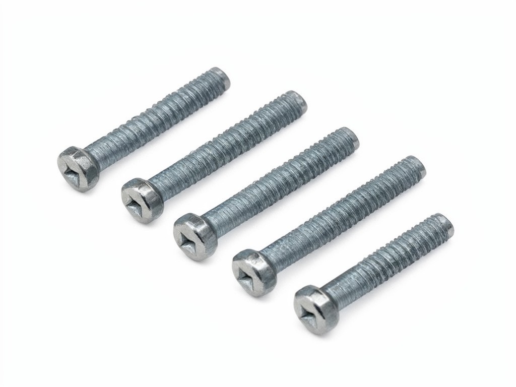
The interface between parts determines whether an M5 x 50 mm countersunk fastener seats flush or loads the surrounding material unevenly. The nominal thread diameter is 5 mm; specify whether the 50 mm length is measured from the top of the countersunk head to the tip, as is common for this form, and confirm the measurement convention on the approved drawing.
Supply can be defined by material, strength class where applicable, thread pitch, head angle, drive recess and surface finish. “Countersunk bolt” is not enough to lock a repeat order: mating-hole geometry and the required drive tool must also match. The common coarse metric pitch is 0.8 mm, but the drawing or purchase specification should govern.
What the Design Has to Balance
Balance and load analysis shows why head fit and material choice belong in the same specification. A mismatched countersink can leave the head proud or concentrate load at the rim; excessive tightening can damage the recess, mating surface or threads before the joint reaches its intended clamp condition.
Cold heading forms the head, while thread rolling is a practical production route for the external thread. Standard head and drive tooling usually keeps setup expense lower. A non-standard angle, recess or head profile can require dedicated tooling and gauges, which raises the initial cost; the quantity ordered determines how much of that cost sits in each piece.
| Construction route | Fit for use | Cost and selection note |
|---|---|---|
| Carbon steel with a specified protective coating | Enclosed or controlled environments where the coating remains intact and the required joint strength is confirmed. | Often a lower-cost route. Coating thickness and coverage can affect thread fit and head seating. |
| Stainless steel, such as an agreed A2 grade | Assemblies exposed to moisture or outdoor conditions, subject to the actual chemical and corrosion exposure. | Material cost is usually higher. Specify grade and assembly practice; stainless threads can gall under some tightening conditions. |
Measured Performance in Real Use
Joint performance depends on the mating material, hole preparation, engagement length and installation torque, not on bolt length alone. For a flush appearance and repeatable assembly feel, inspect head dimensions and seating against the customer’s countersink profile, then verify drive engagement with the production tool.
Incoming and in-process checks can cover overall length, thread diameter and pitch, head geometry, recess condition and finish coverage. Thread gauges and a countersink seating gauge help catch fit deviations; a torque audit on the specified mating parts can reveal recess damage or inconsistent installation behaviour. Salt-spray evaluation is appropriate only when the buyer defines the exposure and acceptance criteria in advance.
Weather resistance is a material-and-finish decision, not a blanket property of the size. Scratches, cut edges and contact with dissimilar metals can change corrosion behaviour, so the final assembly conditions should guide finish approval.
Who Uses It and Where It Matters
OEM buyers use this size where a long threaded section and a flush head are required in an assembled product. Furniture and fixture manufacturers may select it for panel or bracket joints that must present a smooth face; equipment builders may use it on covers and frames where moisture exposure, service access and repeat assembly affect material and drive selection.
Retail and wholesale buyers need a stable, clearly described configuration so customers do not substitute a different pitch, head angle or drive. For exposed installations, confirm the fastener’s material and finish against the expected weather and cleaning conditions before setting the assortment.
OEM and ODM Programme Structure
A repeat programme starts with a controlled drawing or sample that records every interface dimension, material, finish and inspection point. For a standard configuration, shared production tooling can reduce setup charges and shorten the route to production. Custom head geometry or a special recess may call for dedicated forming tools and inspection gauges, so buyers should weigh that upfront spend against forecast volume and the cost of fit-related returns.
Larger, scheduled releases can spread tooling amortisation across more pieces and give the factory a clearer basis for reserving material and production time. Smaller or irregular orders may carry a higher unit cost and longer planning window when they interrupt a standard run. Confirm sample approval, revision control, annual demand and release quantities before fixing price and lead-time terms.
How Consistency Is Held Across Batches
Consistency depends on using the approved drawing, material description and finish specification as the production reference for every release. Tool wear can shift head or recess dimensions, while changes in coating build can affect thread fit. Inspection frequency should reflect those risks and the buyer’s acceptance plan.
A practical control sequence checks first-off parts after setup, monitors critical dimensions during the run and retains batch identification for later investigation. Material and finish substitutions require approval rather than an informal purchasing change. Where warranty claims have traced back to loose fit or damaged drives, add the relevant mating-part check and assembly-tool condition to the agreed control plan.
Keeping Repeat Orders Supplied
Availability depends on the exact material, finish and production route; a familiar M5 x 50 mm size does not mean every head, drive and coating combination is held as stock. Buyers with repeat demand can reduce supply gaps by agreeing forecast releases and preserving one approved specification instead of rotating near-equivalent alternatives.
For a new or revised configuration, start with a tooling review of the drawing, countersink interface, drive and expected order volume. Request a tooling review and discuss a repeat-order plan before sample approval, so the quoted unit cost and lead-time assumptions reflect the actual production setup.