


Custom m6 x 35mm hex bolt supplier: Specification, Ordering and Quality Notes
The interface between parts determines whether an M6 × 35 mm hex bolt seats cleanly, holds clamp load and can be removed for service. A nominal diameter and length alone do not define that fit: thread form, head dimensions, finish thickness and the mating part all affect assembly. Approve the drawing against the joint, then freeze the inspection points before production.
Design Constraints Behind the Specification
For a conventional metric coarse thread, M6 commonly uses a 1.0 mm pitch; confirm the pitch on the buyer’s drawing rather than assuming it from the diameter. The 35 mm dimension normally means length from the underside of the head to the end of the bolt. Head style, across-flats dimension, thread length and any point or chamfer detail still need confirmation.
A hex head formed by cold heading and a thread produced by rolling suit repeat production when the part geometry is stable. If the bolt is too long for the available clearance, it can bottom out before clamping the joint; if too short, usable thread engagement falls. Specify the grip stack and mating thread so the supplier can flag a length mismatch before tooling or batch release.
Set the acceptance drawing around the actual assembly: under-head length, thread pitch and class, head dimensions, property class, finish and marking. A finish change can affect thread fit, so confirm the finished-part requirement rather than checking an uncoated sample only.
Where This Product Beats Standard Alternatives
A standard catalogue bolt is a sensible choice when its head, thread, strength class and finish already match the joint. A custom order earns its place when a repeat complaint traces to a defined mismatch: a head that fouls a nearby feature, a finish that wears through in wet service, or a thread length that leaves too little engagement after the parts are clamped.
Changing only the nominal length will not solve a joint that loosens because of incorrect torque practice or a deforming mating surface. Keep the fastener specification tied to the assembly drawing and service conditions. That makes replacements easier to identify and helps purchasing avoid substituting a visually similar bolt with a different thread or coating.
Option Comparison by Usage Level
Choose the production route from the cost of failure and the degree of fit control the assembly needs. Use this decision path to separate a catalogue substitution from a controlled custom order:
- If a standard M6 bolt matches the drawing and service environment, use the catalogue configuration; confirm the finished length, thread and property class before ordering.
- For occasional maintenance demand, standard supply can reduce unit cost and avoid custom setup.
- If mixed supplier lots have caused fit complaints, hold the drawing and acceptance details constant across replenishment orders.
- If the head, thread length, marking or coating must differ from the catalogue part, request a drawing-based quote and a pre-production sample.
- For frequent production use, compare setup cost with the cost of rework, service calls and incorrect replacements.
- Where outdoor exposure is involved, settle the finish and corrosion acceptance requirement before approving the production sample.
Customisation Options and Their Limits
Custom orders can define head dimensions, thread length, point form, property class, surface finish and head marking. Changes to the head or blank geometry may require a new forming setup; special marking and finishing can add a separate production step. The quoted price and lead time depend on which dimensions depart from the supplier’s existing tooling.
Do not treat coating colour as the corrosion specification. Coating type, thickness, handling and the actual exposure all matter, while added finish thickness can tighten thread clearance. Agree the finished thread fit and any corrosion test method before sample approval; avoid specifying an unverified service-life promise in place of an acceptance criterion.
OEM and ODM Programme Structure
An OEM order normally follows the buyer’s released drawing and part requirements. An ODM discussion can begin with a joint constraint—such as restricted head clearance or a corrosion complaint—but the supplier’s proposed geometry still needs buyer engineering approval before manufacture. For either route, send the drawing revision, annual or release quantity, finish requirement, property class and target approval date together.
To protect a retail or equipment launch date, allow time for drawing review, sample manufacture, approval and any required test report. A late change to thread fit or coating after sample sign-off can reset that sequence. Record the approved sample and revision as the production reference for repeat orders.
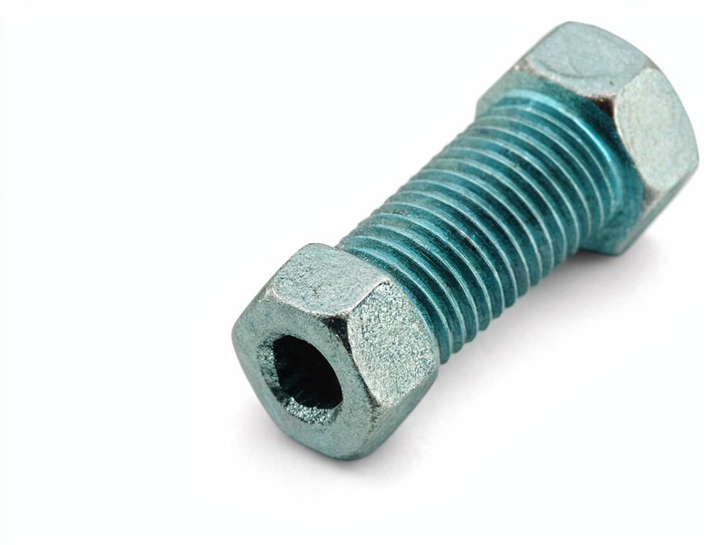
What Gets Checked Before Shipment
Consistency depends on checking the features that cause assembly and field complaints, not appearance alone. A practical inspection plan compares finished parts with the approved drawing and agreed sample. Checks may include under-head length, thread gauging, head across flats, visual finish condition and marking legibility.
Where the order calls for it, verify coating thickness with a suitable measurement method and assess corrosion resistance against the agreed test conditions. A torque or clamp-load check should use the mating parts and assembly method specified by the buyer; a generic torque figure is not a substitute for that setup. Confirm the inspection frequency and reporting format before the production lot is released.
Stock Availability and Reorder Planning
Stock status depends on the exact configuration, not only on the M6 × 35 mm size. Standard head and thread forms may be available sooner than a non-standard finish, marking or geometry; confirm the drawing revision and available quantity before tying a launch date to a purchase order. Custom production lead time also depends on approval timing and any finishing or testing steps.
For reorders, keep the part number, finish, property class and approved revision aligned with the first release. Forecasting repeat demand early gives the supplier time to reserve production capacity, while a call-off plan can reduce the risk of an urgent substitute entering the assembly line.
Care, Storage and Service Life
Corrosion complaints often begin at damaged coating, trapped moisture or a finish chosen without regard to the exposure. Service life depends on the joint environment and installation condition, so inspect the fastener and mating surfaces during scheduled maintenance. Replace bolts with damaged threads, deformed heads or coating loss that exposes the base metal where corrosion is a concern.
| Service condition | Likely first complaint | Specification or maintenance response |
|---|---|---|
| Dry indoor assembly with routine service access | Rounded hex corners after repeated tool use | Confirm head dimensions and tool clearance; use the specified tool and replace visibly deformed fasteners. |
| Intermittent outdoor rain or condensation | Rust staining or coating damage near the head and thread | Specify a finish for the exposure and thread fit; inspect for coating damage and trapped moisture during service. |
| Repeated removal and reinstallation | Thread wear, cross-threading or loss of clamp | Start threads by hand, follow the assembly torque procedure and replace bolts that no longer engage smoothly. |
Request a sample against your drawing before placing the production order. Include the mating-part details, finish and target approval date so the fit and inspection plan can be reviewed against the launch schedule. Send a sample request.